

A 138 kV line trips at 2:10 in the morning and recloses successfully. By the time the protection engineer sees the SCADA alarm, the event is already history, and the oscillography that explains it sits in four relays at the station: two line relays, the bus differential, and a transformer relay. Somebody will pull those files. Maybe a technician on the next scheduled visit, maybe an engineer through a dial-up or jump-host session that takes an afternoon to arrange. Meanwhile, the DGA monitor on the station’s main transformer has shown acetylene creeping up for six weeks, but its readings live in a vendor portal that the asset group checks once a month. The station battery charger has been sitting at the wrong float voltage since a breaker test last spring.
That is what substation data looks like at most utilities, co-ops, and munis: the measurements exist, often in monitoring IEDs bought for exactly this purpose, but they sit in separate boxes and portals, and nobody sees them together until something has gone wrong.
The cost of that gap is set by the equipment you can least afford to lose. A large power transformer, which DOE defines as 100 MVA and up, typically weighs between 150 and 400 tons, and DOE’s 2024 resilience report found 36-month lead times commonly quoted, with some reaching 60 months [1]. DOE’s earlier study found that only about 30 Schnabel railcars in North America can carry the heaviest units [2], and GAO put the purchase price as high as $10 million, with moving costs in the hundreds of thousands [3]. Wood Mackenzie measured average power transformer lead times at about 120 weeks in 2024, up from roughly 50 weeks in 2021, with prices up 60 to 80 percent since early 2020 [4]. Utility Dive, reporting on NREL and NIAC work, described waits of up to three years for new large units [5]. When a unit like that fails without warning, the utility does not get a new one this year.
This paper covers what is worth measuring, an architecture that keeps data in the substation and monitoring apart from protection, a station-by-station rollout starting with what you already own, where these projects go wrong, and which NERC CIP requirements apply.
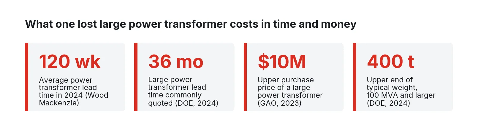
Figure 1. Lead time, price, and weight of large power transformers. Sources: Wood Mackenzie (2024), DOE Large Power Transformer Resilience Report (2024), GAO-23-106180 (2023).
A self-check for one substation
Pick one transmission or distribution substation you know well and try to answer these from your desk, today, without sending anyone into the yard.
- For the last relay operation at that station, how long did it take to get the COMTRADE files from every IED that saw the fault into one folder, and who did it?
- Do you have a current, as-built SCD file for the station, and does it match what is actually configured in the relays?
- What were the last three DGA results on the station’s largest transformer, what is the rate of change of each key gas, and is anyone looking at rate as well as level?
- For each bushing above 69 kV, when was the last power factor and capacitance measurement, and is anything online between tests?
- For the breakers that protect that transformer, do you know the trip coil current signature and the last operating time, and how many operations since the last overhaul?
- What is the station battery’s float voltage right now, and what PRC-005 activity would that answer let you skip?
- If a vendor needed remote access to a monitoring device tomorrow, how would the session be established, logged, and ended, and what would your CIP program call that connection?
Most stations can answer one or two quickly. The rest are scattered across file shares, portals, and paper test reports.
What needs to be measured and where it comes from
Condition data comes from the P&C IEDs already in the station, monitoring IEDs added to the most valuable assets, and station auxiliaries. The table lists the signals that earn their keep and how each is read.
| Signal | Typical source | How it is read | Why it matters |
|---|---|---|---|
| Fault records (oscillography) | Line, bus, transformer relays; DFRs | COMTRADE files via MMS file transfer, DNP3 file transfer, or vendor tools | Root cause of every operation and misoperation |
| Sequential events (SER/SOE) | Relays, RTU | MMS reports, DNP3 event classes | Order of contacts, timing, breaker failure |
| Dissolved gases, moisture in oil | Online DGA monitor, lab results | Modbus, DNP3, or IEC 61850 MMS; lab files | Early sign of thermal faults and arcing in tank and OLTC |
| Bushing C1 capacitance, power factor, PD | Bushing monitor at test tap | MMS or DNP3 | Bushings start a large share of failures and fires |
| Top-oil and winding temperature, load | Transformer monitor, relay metering | MMS, DNP3 | Loading against insulation aging |
| OLTC operation count, motor current | Tap changer controller or monitor | MMS, DNP3, Modbus | OLTC is the second most common failure location |
| Breaker trip and close coil current, operating time | Breaker monitor, relay | MMS, DNP3, COMTRADE | Mechanism problems show before a failure to open |
| SF6 density, operation counts | Breaker monitor, density relay | MMS, DNP3 | Leaks and wear |
| Battery float voltage, charger current, cell ohmic values, temperature | Battery monitor, charger | Modbus, DNP3 | Protection depends on the DC system |
| Station configuration | SCD file | IEC 61850-6 SCL | Names, ratios, and data models for everything above |
IEC 61850 is three different things on the wire
IEC 61850-8-1 maps the abstract model to MMS for client/server traffic and to Ethernet frames for time-critical messages [23]. In practice, a station has three kinds of traffic. MMS is the client/server path that SCADA gateways, engineering tools, and monitoring clients use to read data, receive buffered and unbuffered reports, and retrieve files. GOOSE is the multicast peer-to-peer path that relays use for interlocks, breaker failure initiation, and tripping. Sampled values carry digitized current and voltage from merging units on a process bus. Many stations also carry DNP3, defined in IEEE 1815, on the RTU or gateway path to SCADA [25]. A monitoring system needs MMS or DNP3 reads. It has no business publishing GOOSE or sampled values, and it should never be a subscriber whose behavior can affect a protection function.
The configuration that ties those together lives in SCL files defined by IEC 61850-6, which describes IED capabilities, communication configuration, and the switchyard structure in a format tools from different vendors can exchange [22]. The station’s SCD file is the most useful document a monitoring project can have: every logical node, data object, and report control block, with names the P&C group already uses.
COMTRADE is the common language of events
IEEE C37.111, also published as IEC 60255-24, defines the COMTRADE format for transient and event data: a configuration file describing channels and sample timing plus a data file of samples, with the 2013 edition adding binary and floating-point formats and a single-file option [26]. Every relay vendor exports it; the work is in retrieving it from every IED that saw the fault and grouping the files by event.
Why condition data on these assets pays
The CIGRE working group A2.37 reliability survey, covering 964 major failures across 167,459 transformer-years at 58 utilities in 21 countries, found an overall substation transformer failure rate of about 0.53 percent per year [6]. Of 536 substation transformer failures with a known location, 38 percent started in the windings, 31 percent in the on-load tap changer, and 14 percent in bushings. The survey also found a fairly constant hazard rate with no distinct bathtub shape, which the authors read as an argument for maintenance based on condition rather than age [6].
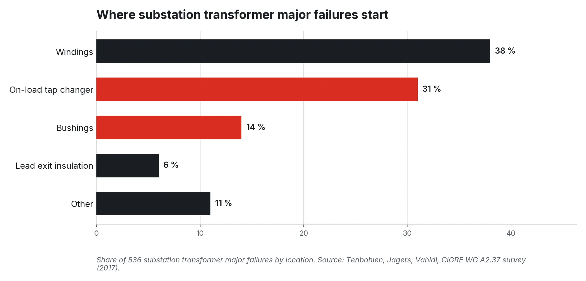
Figure 2. Location of substation transformer major failures. Source: Tenbohlen, Jagers, and Vahidi on behalf of CIGRE WG A2.37 (2017), 536 failures with known location.
Bushings deserve separate attention. EPRI’s 2023 investigation estimated bushings at roughly 17 to 20 percent of transformer failures globally and about 30 percent of generator step-up failures, and noted that continuous online monitoring and trending with set alarm points are the way to catch degradation between outages [7]. CIGRE’s bushing working group described bushing failures as the most common cause of transformer fires [8].
For DGA, the important change is IEEE C57.104-2019. The guide moved away from a single table of fixed gas limits to 90th and 95th percentile norms conditioned on transformer age and oxygen-to-nitrogen ratio, and it gives rate of change equal weight with level [20]. The working group’s own flowchart assigns DGA status by whether any gas and any rate exceed the 95th percentile [21]. As one DGA software vendor’s explainer puts it, level-only screening does half of what the guide describes, and acetylene counts on any increase [20]. Rates need regular samples, which online monitors provide.
Breakers fail differently. CIGRE’s earlier circuit breaker surveys found about 70 percent of major failures were of mechanical origin, with the operating mechanism the single largest contributor at 37 percent, and the most common major failure modes were “does not open or close on command” and “locked in open or closed position” [9]. Trip coil current signatures and operating times recorded by relays and breaker monitors are the direct evidence of a mechanism slowing down.
The station battery is the quiet one. PRC-005-6 sets maintenance intervals for station DC supply, including four-month checks of voltage, electrolyte level, and grounds on vented lead-acid batteries, and it allows monitoring with alarming to replace some of those periodic activities, such as charger voltage verification when voltage is monitored and alarmed [17]. IEEE 1188-2025 covers maintenance and testing of VRLA batteries, including guidance on premature capacity failures [27].
Finally, protection itself. NERC tracks protection system misoperations because nearly all major system failures other than severe weather have relay or control misoperations as a contributing factor [19]. ReliabilityFirst reported 133 misoperations out of 1,843 protection system operations in 2024, a 7.22 percent rate, with relay failure, incorrect settings, unknown causes, and as-left errors leading the list [18]. NERC’s 2025 State of Reliability rated the misoperation rate as improving or stable overall [28]. Every misoperation investigation still starts with event records. “Unknown” is often a record that was never retrieved.
Reference architecture
The design principle is simple to state and easy to violate: monitoring reads, protection protects, and nothing in the monitoring system can change what a relay does.
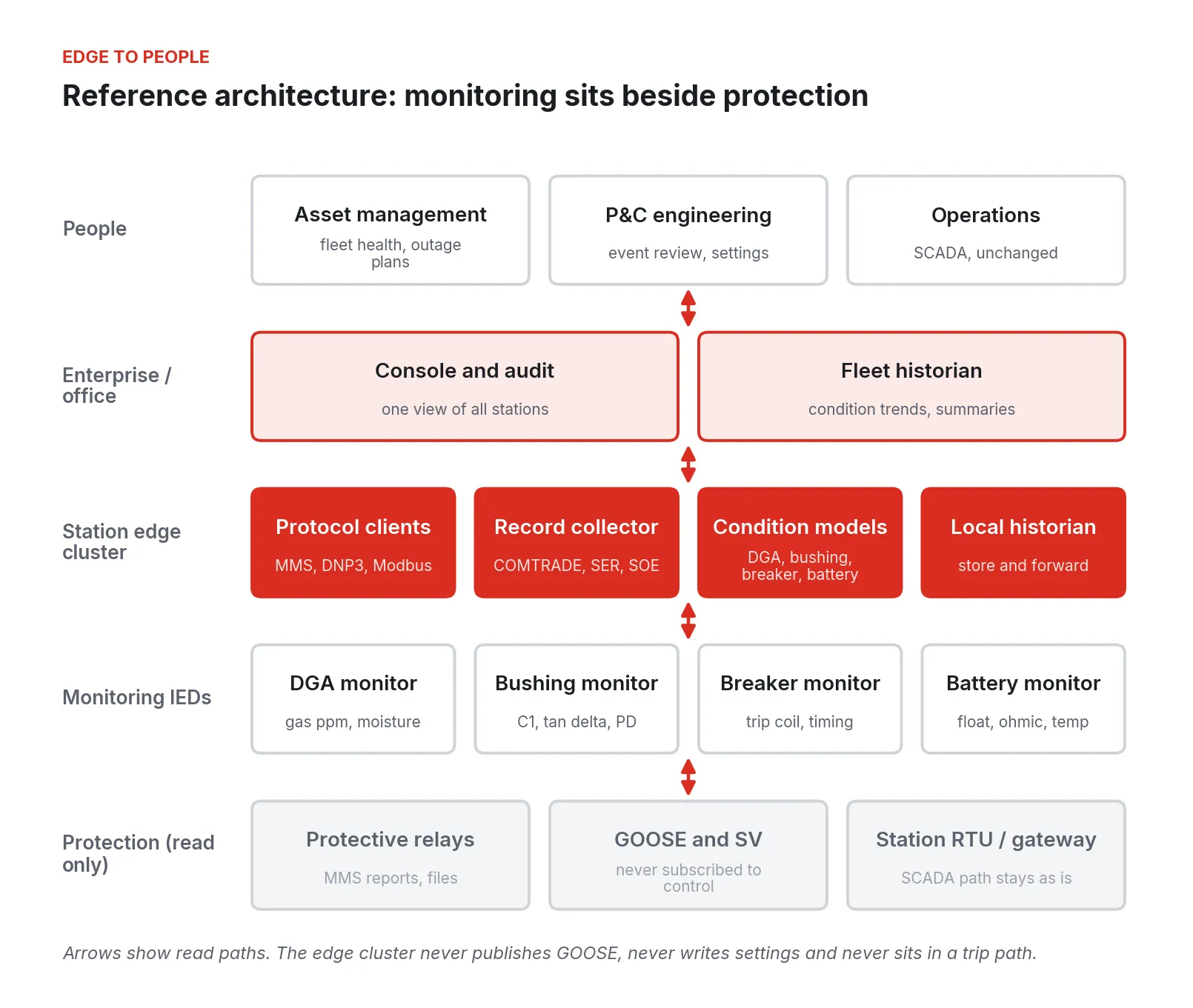
Figure 3. Reference architecture. A small edge cluster in the station reads monitoring IEDs and relays over MMS, DNP3, and Modbus, keeps the data locally, and forwards summaries. It does not publish GOOSE, write settings, or sit in any trip path.
From the bottom up:
1. Protection, read only. Relays keep their settings, their GOOSE, and their trip outputs. The monitoring cluster connects as an MMS client with a read-only role, or reads DNP3 from an existing port that is already configured for it. The SCADA path through the station RTU or gateway stays exactly as it is.
2. Monitoring IEDs. DGA, bushing, breaker, and battery monitors speak Modbus, DNP3, or IEC 61850 depending on vintage. Each one becomes a source with a known address, tag list, and poll rate.
3. Station edge cluster. Two or three small industrial computers in the control house run the protocol clients, a record collector for COMTRADE and SER, a local historian, and the condition models: DGA screening to C57.104, bushing trend alarms, breaker timing comparisons, and battery checks. Models run where the data is, so a lost link does not stop detection.
4. Enterprise and people. A console and fleet historian give asset management condition trends, P&C engineering event packets, and leave operations’ SCADA as it is. Raw oscillography can stay in the station until someone asks for it.
Walking the work, cheapest first
Step 1: Inventory and the SCD file
Start with the station’s SCD file and the relay list. Reconcile them: which IEDs are in the file, which are actually on the network, which firmware is loaded. It costs a few days of engineering time and surfaces the drift between design and as-built that every later step depends on.
Decide the CIP category of the station with your CIP group before anything is connected. A low impact station under CIP-003 and a medium impact station under CIP-005, -007, and -010 lead to different designs for the same monitoring function (see the security section).
Step 2: Event records you already own
Relays already capture oscillography and SER on every operation. Automating retrieval is the fastest win in this whole program because it needs no new sensors. The collector watches for new records over MMS file services or DNP3, pulls them, renames them consistently, attaches channel names and ratios from the SCD file, and groups all files from one fault into one event packet.
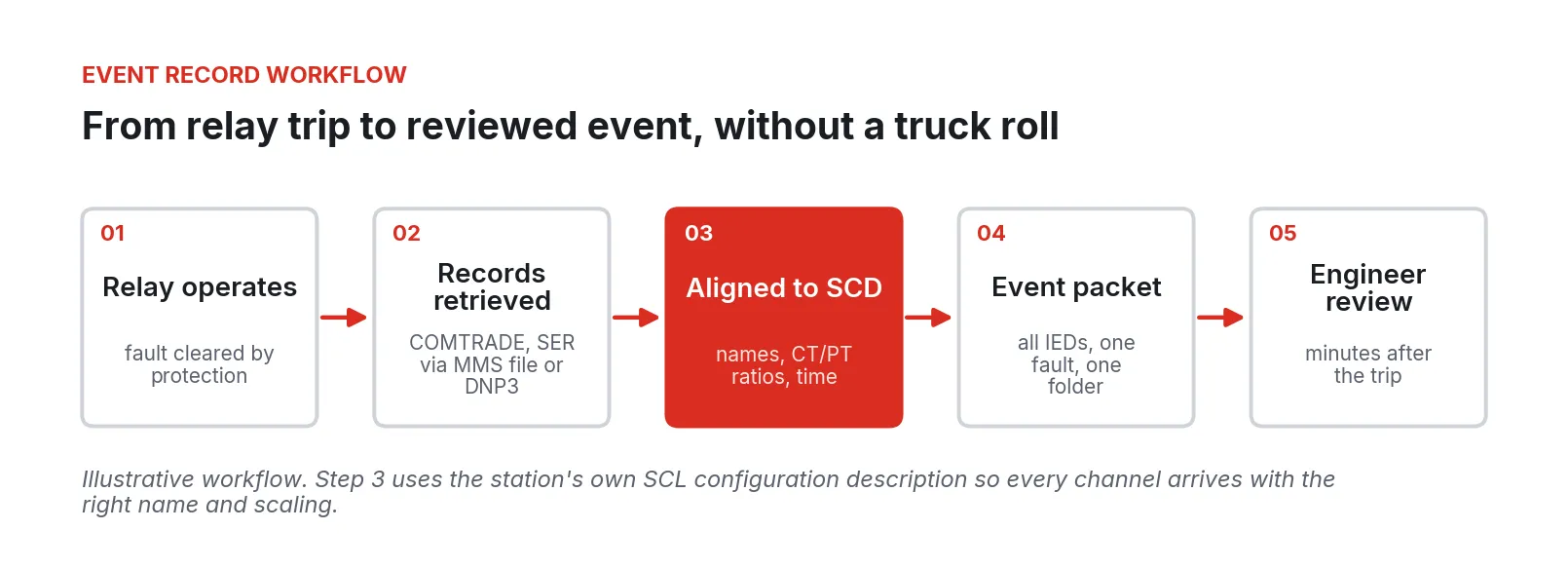
Figure 4. Event record workflow (illustrative). Records are retrieved automatically after an operation, aligned to the station’s SCD file, and grouped into one packet per fault.
For misoperation analysis, it is often the difference between a cause and “unknown”.
Step 3: Transformer condition
Connect the existing DGA and bushing monitors to the cluster instead of, or in addition to, their vendor portals. Import lab DGA results with oxygen and nitrogen, since C57.104-2019 needs the O2/N2 ratio and transformer age to pick the right norms [20]. Compute both level and rate status for each gas. Trend bushing C1 and power factor against the nameplate and the last offline test, with alarm points the asset engineer sets.
Where a large transformer has no online monitor, rank candidates for one by consequence: no spare, long replacement path, history of gassing.
Step 4: Breakers and batteries
Breaker trip coil current and operating time are often already available in the relay that trips the breaker. Pull them on every operation and compare each one to that breaker’s own history. A slowly lengthening operating time on a transformer breaker can be handled as a planned work order if you see it early.
Battery monitors and charger data come last because they are cheap and simple. Their payoff is direct: continuous float voltage and ohmic values, with alarming, change which periodic PRC-005 activities your program still has to perform by visit [17].
Where these projects go wrong
1. Monitoring creeps into protection. A client gets write access “just for testing”, or a breaker monitor ends up in a trip circuit. Either makes monitoring part of protection, with the testing and CIP consequences that follow. Write the rule down: read-only roles, no GOOSE publication, no control outputs.
2. The SCD file is wrong. Names do not match the relays, or scaling is off by a CT ratio, and every alarm downstream is suspect.
3. Polling too hard. Older relays have limited MMS association and file-transfer capacity. A monitoring client that polls every data point every second, or pulls large records during a fault, competes with SCADA. Use reports where supported and poll slowly.
4. Fixed-limit DGA screening. Tables copied from older editions of C57.104 produce false alarms on sealed units and miss real gas production on free-breathing ones, and level-only screening misses rate entirely [20].
5. Portals that nobody reads. Monitoring IEDs bought with capital money report to vendor web pages that are checked monthly at best. The data is there; the attention is not.
6. Unplanned remote access. A vendor needs into a monitor and a cellular modem appears in the control house. That is how a monitoring project creates a CIP finding.
7. Model alarms nobody trusts. Anomaly models that fire on every load swing get switched off. Start with the IEEE guides’ rule-based methods and add learned models only where they beat those rules on your data.
Security and NERC CIP
The utility’s CIP program owns compliance: categorization, the plans, the evidence, and the audit. The architecture’s job is to make the required controls straightforward to implement and to produce evidence as a by-product. Here is how each relevant standard applies.
Figure 5. NERC CIP requirements that apply to a substation monitoring cluster and how the architecture supports each. The utility’s CIP program determines applicability and owns compliance.
CIP-002: categorization
CIP-002 Attachment 1 sets the bright lines. A transmission facility at a substation operated at 500 kV or higher is medium impact, as is a 200 to 499 kV station connected to three or more other stations above an aggregate weighted value of 3,000; substations critical to IROLs or nuclear plant interface requirements are also medium impact [10]. Transmission stations that meet none of the criteria are low impact, and the identifications are reviewed at least every 15 calendar months [10]. Whether the monitoring cluster is itself a BES Cyber System, a Protected Cyber Asset inside an Electronic Security Perimeter, or out of scope is the utility’s determination. Make it before the hardware is installed.
CIP-003: low impact stations
Most distribution and many sub-transmission substations are low impact. CIP-003 Attachment 1 requires electronic access controls that permit only necessary inbound and outbound routable communications between low impact systems and anything outside the asset, with an exclusion for time-sensitive protection functions [11]. CIP-003-9, effective April 1, 2026, adds Section 6 on vendor electronic remote access: a method to determine vendor remote access sessions, a method to disable it, and a method to detect malicious communications during it [16]. Section 5 covers transient cyber assets such as the laptop a technician plugs into a relay [11].
A cluster with outbound-only connections, no inbound ports, and identity-logged sessions that can be ended from a console gives the CIP program a concrete method for each section; the program still writes the plan and keeps the evidence.
CIP-005: perimeters and Interactive Remote Access
At medium impact stations with External Routable Connectivity, CIP-005-7 requires every routable connection to pass through an identified Electronic Access Point with deny-by-default rules; Interactive Remote Access must use an Intermediate System, with encryption terminating at that system and multi-factor authentication; and the entity needs methods to determine and disable active vendor remote access sessions [12]. CIP-005-8, approved in 2024 as part of the virtualization modifications, adds requirements for shared cyber infrastructure and prevents an Intermediate System from sharing CPU and memory with high or medium impact BES Cyber Systems [13].
So a zero-trust tunnel does not replace the Intermediate System. That system belongs on separate hardware outside the ESP, and the EAP should allow the cluster only the outbound connections the program has justified.
CIP-007: system security management
CIP-007-6 asks for only the logical ports that are needed, evaluation of security patches at least every 35 calendar days, malicious code prevention, logging of logins and failed attempts with 90 days of retention and review every 15 days, and authentication and password controls on interactive access [14]. A minimal operating system with a built-in firewall shortens the port list to justify, and image-based patching with rollback makes the 35-day cycle practical across a fleet.
CIP-010: configuration and transient assets
CIP-010-4 requires a baseline of operating system, firmware, software, ports, and patches, authorization and documentation of changes, verification that CIP-005 and CIP-007 controls survive each change, vulnerability assessments at least every 15 calendar months, and plans for transient cyber assets and removable media [15]. An immutable image is a baseline by construction: the running system is the image that was approved, and any change is a new image with a record.
IEC 62351 for the IEC 61850 traffic itself
Inside the station, IEC 62351 is the security series for IEC 61850. IEC 62351-4 covers MMS, IEC 62351-6 covers GOOSE and sampled values (authentication required for the routable forms), IEC 62351-8 adds role-based access, and IEC 62351-9 handles key management [24]. Where relays support roles, give the monitoring client a read-only one; elsewhere, segmentation carries the load.
Phased rollout
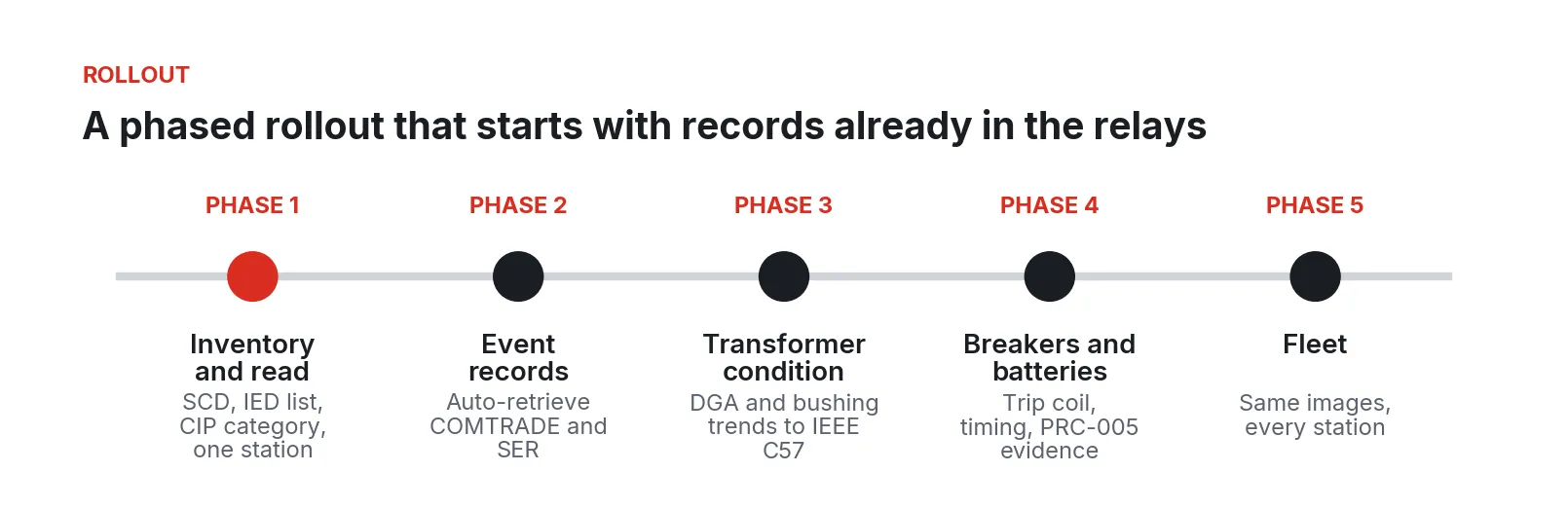
Figure 6. A five-phase rollout, starting with one station and the event records its relays already capture.
Each phase is the matching step above, applied to one station before the next. Phase 1 should take weeks, not months; the fleet phase follows the order set by transformer consequence and CIP category, and every later station reuses the same images with its own SCD file and tag list.
What to do Monday
Pick the substation whose main transformer you would least like to replace. Find its SCD file and check it against the relays that are actually installed. Ask your CIP group to write down the station’s category and what a monitoring device on that network would be classified as. Then pull the event records from the last three operations at that station by hand, time how long it takes, and put the results next to the transformer’s last three DGA samples, rate and level both. That one page will show which data nobody is looking at and whether Phase 2 or Phase 3 comes first.
None of this needs new protection, a control system migration, or a capital request to start. It needs one station, the files you already own, and an agreement with the CIP group on how monitoring connects.
Fireball Industries is EmberNet’s master integrator. Fireball designs, builds, and supports substation monitoring systems on EmberNet, from SCD reconciliation and read-only IED integration through the edge cluster, condition models, and the remote access design your CIP program approves, and stays with the utility as the fleet grows.
Sources
- U.S. Department of Energy, “Large Power Transformer Resilience: Report to Congress,” July 2024. https://www.energy.gov/sites/default/files/2024-10/EXEC-2022-001242%20-%20Large%20Power%20Transformer%20Resilience%20Report%20signed%20by%20Secretary%20Granholm%20on%207-10-24.pdf
- U.S. Department of Energy, Office of Electricity Delivery and Energy Reliability, “Large Power Transformers and the U.S. Electric Grid,” June 2012. https://www.energy.gov/sites/prod/files/Large%20Power%20Transformer%20Study%20-%20June%202012_0.pdf
- U.S. Government Accountability Office, “Electricity Grid: DOE Could Better Support Industry Efforts to Ensure Adequate Transformer Reserves,” GAO-23-106180, August 2, 2023. https://www.gao.gov/products/gao-23-106180
- Sagar Chopra and Benjamin Boucher, Wood Mackenzie, “Supply shortages and an inflexible market give rise to high power transformer lead times,” April 2, 2024. https://www.woodmac.com/news/opinion/supply-shortages-and-an-inflexible-market-give-rise-to-high-power-transformer-lead-times/
- Herman K. Trabish, Utility Dive, “Transformer supply bottleneck threatens power system stability as load grows,” February 12, 2025. https://www.utilitydive.com/news/electric-transformer-shortage-nrel-niac/738947/
- Stefan Tenbohlen, Janine Jagers and Farzaneh Vahidi, “Standardized survey of transformer reliability: On behalf of CIGRE WG A2.37,” 2017. https://www.researchgate.net/publication/321660440_Standardized_survey_of_transformer_reliability_On_behalf_of_CIGRE_WG_A237
- EPRI, “Transformer Bushing Failure Investigation: High-Voltage Oil-Impregnated Paper Bushing Reliability, Operational, and Safety Concerns,” 2023 white paper, August 2023. https://restservice.epri.com/publicdownload/000000003002026357/0/Product
- CIGRE Study Committee A2, “Terms of Reference, WG A2.43: Transformer bushings reliability,” approved June 15, 2010. https://www.cigre.org/userfiles/files/News/2018/TOR_WG_A2_43_Transformer_bushings_reliability_Um_72,5_kV.pdf
- Carl E. Sölver, “Past Cigré surveys on reliability of HV equipment,” CIGRE WG A3.06 presentation, n.d. https://mtec-llc.com/cigre_a3_06/Rio/past.pdf
- NERC, “CIP-002-5.1a: Cyber Security, BES Cyber System Categorization.” https://www.nerc.com/pa/Stand/Reliability%20Standards/CIP-002-5.1a.pdf
- NERC, “CIP-003-9: Cyber Security, Security Management Controls.” https://www.nerc.com/pa/Stand/Reliability%20Standards/CIP-003-9.pdf
- NERC, “CIP-005-7: Cyber Security, Electronic Security Perimeter(s).” https://www.nerc.com/globalassets/standards/reliability-standards/cip/cip-005-7.pdf
- NERC, “CIP-005-8: Cyber Security, Electronic Security Perimeter(s),” Project 2016-02 virtualization modifications, approved May 9, 2024. https://www.nerc.com/globalassets/standards/reliability-standards/cip/cip-005-8.pdf
- NERC, “CIP-007-6: Cyber Security, System Security Management.” https://www.nerc.com/pa/Stand/Reliability%20Standards/CIP-007-6.pdf
- NERC, “CIP-010-4: Cyber Security, Configuration Change Management and Vulnerability Assessments.” https://www.nerc.com/pa/Stand/Reliability%20Standards/CIP-010-4.pdf
- Lew Folkerth, ReliabilityFirst, “The Lighthouse: CIP low impact from the ground up, Part 8: 3.9 electronic access controls for CIP-003-9,” updated August 19, 2026. https://www.rfirst.org/resource-center/the-lighthouse-cip-low-impact-from-the-ground-up-part-8-3-9-electronic-access-controls-for-cip-003-9/
- NERC, “PRC-005-6: Protection System, Automatic Reclosing, and Sudden Pressure Relaying Maintenance.” https://www.nerc.com/pa/Stand/Reliability%20Standards/PRC-005-6.pdf
- Thomas Teafatiller, ReliabilityFirst, “ReliabilityFirst 2024 Misoperation Performance and Improvement Opportunities,” October 15, 2025. https://www.rfirst.org/resource-center/reliabilityfirst-2024-misoperation-performance-and-improvement-opportunities/
- NERC, “M-9 Protection System Misoperations,” reliability indicator page. https://www.nerc.com/programs/reliability-assessment--performance-analysis/reliability-indicators/m-9-protection-system-misoperations
- Massimiliano Vurro, Seeta Labs (DGA software vendor), “Normal Dissolved Gas Levels in Transformers: Why Fixed DGA Limits Are Obsolete,” July 19, 2026. https://seetalabs.com/normal-dissolved-gas-levels-in-transformers/
- IEEE PES Transformers Committee, Working Group C57.104, Fall 2024 meeting presentation. https://grouper.ieee.org/groups/transformers/subcommittees/fluids/C57.104/F24-C57.104-MtgPresentation.pdf
- IEC, “IEC 61850-6:2009+AMD1:2018 CSV: Configuration description language for communication in power utility automation systems,” June 7, 2018. https://webstore.iec.ch/en/publication/63319
- IEC, “IEC 61850-8-1:2011: Specific communication service mapping (SCSM), Mappings to MMS and to ISO/IEC 8802-3,” June 17, 2011. https://webstore.iec.ch/en/publication/6021
- Christoph Brunner, PAC World, “Securing IEC 61850,” August 10, 2022. https://www.pacw.org/securing-iec-61850
- IEEE, “IEEE 1815-2012: IEEE Standard for Electric Power Systems Communications, Distributed Network Protocol (DNP3),” October 10, 2012. https://standards.ieee.org/ieee/1815/5414/
- Wikipedia, “Comtrade” (summary of IEEE C37.111 / IEC 60255-24 file formats). https://en.wikipedia.org/wiki/Comtrade
- IEEE, “IEEE 1188-2025: Recommended Practice for Maintenance, Testing, and Replacement of Valve-Regulated Lead-Acid (VRLA) Batteries for Stationary Applications.” https://standards.ieee.org/ieee/1188/11656/
- NERC, “2025 State of Reliability: Overview of 2024 Bulk Power System Performance.” https://www.nerc.com/globalassets/programs/rapa/pa/nerc_sor_2025_overview.pdf