

The monthly availability report comes back with a hole in it. Inverter 14 at a 100 MW solar site shows zero output for most of the 9th through the 12th, the cellular modem in the substation control house was also down for part of that window, and nobody can say whether the inverter tripped or the data simply never arrived. The O&M contractor says the unit was running. The revenue meter says the site was a little short. The inverter OEM wants logs before it will talk about a warranty claim, and the logs live on a data logger that overwrote its buffer two days into the outage. Someone will spend a week reconstructing four days.
Every renewable asset manager has a version of this story; the wind version swaps in a turbine controller and a satellite terminal. The problem is rarely the equipment alone. It is a SCADA layer handed over by the EPC at commercial operation, built for the punch list rather than for twenty-five years of operation, sitting at the end of a backhaul link that fails more often than anyone budgeted for. When the link drops, the site keeps generating, but the record of what it generated, and why it stopped, goes missing.
That missing record costs money three ways: real outages become arguments that delay warranty and availability-guarantee claims, failures stay hidden until someone drives out, and the owner cannot show a regulator who touched the plant’s control systems, from where, and when.
This paper covers what to measure, how data and control should flow, the order to do the work in, where these projects go wrong, and how the architecture lines up with NERC CIP-003-9. Most of it can start with the equipment already on site.
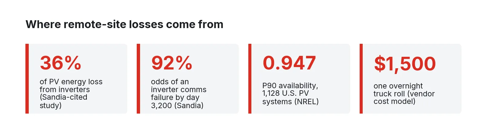
Figure 1. Four numbers that frame the problem. Sources: Gunda et al., Sandia/NREL (2020), citing a 3,500-record study; Deline et al., NREL (2024); Power Factors (2018), one vendor’s cost model.
A self-check for your own fleet
Answer these for one site, today, without opening a ticket.
- When the backhaul at your most remote site last went down, how many hours of inverter or turbine data did you lose for good, and how many came back later?
- For last month’s lowest-availability unit, can you separate real downtime from communications downtime using data you already hold, or does it take a site visit?
- How many distinct devices at the site can be reached from outside the fence, by whom, and could you turn each of those paths off in under ten minutes?
- Which firewall rule set protects the plant controller and the turbine or inverter network, when was it last reviewed, and who signed off on the change?
- If the SCADA server in the control house failed tonight, could you rebuild it from documentation, or is the EPC’s original image the only copy?
- How many truck rolls last quarter were to reset, reboot, or simply look at something that a working remote path would have shown you?
- Do your OEM service providers connect through your access path, or through their own modem, VPN appliance, or cloud portal?
If more than two answers are “I don’t know”, the site is running on its equipment and luck.
What needs to be measured and connected
A generation site has fewer signal types than a factory, but more owners: inverter OEM, turbine OEM, tracker vendor, the EPC’s SCADA integrator, the utility, and the O&M contractor, each with its own protocol and its own idea of what “available” means.
The standards help where they are used. On the solar side, the SunSpec Alliance’s 700-series information models (701 through 713) cover AC measurements, capacity, enter-service settings, volt-var, volt-watt, ride-through trips, and frequency droop, and they are referenced in IEEE 1547-2018. On the wind side, IEC 61400-25 was written specifically because wind plants were running on proprietary protocols with incompatible labels and semantics; it defines a common information model for turbines and maps it onto IEC 61850 MMS, IEC 60870-5-104, DNP3, OPC XML-DA, and web services. Substation communication stays under IEC 61850. Most fleets have a mix: a newer site that speaks SunSpec, an older one with vendor register maps, and a wind site whose turbine data only leaves through the OEM’s SCADA.
| Source | Typical interface | Signals that matter | Why it matters |
|---|---|---|---|
| Central and string inverters | Modbus TCP or RS-485, SunSpec 700-series where supported | AC power, energy counter, state, fault codes, DC input, cabinet temperature | Inverters are the largest single driver of corrective maintenance and lost energy on PV sites |
| Trackers | Vendor Modbus or proprietary gateway | Row angle, target angle, stow state, motor faults, wind stow events | A stuck row loses energy quietly and never shows as an inverter fault |
| Turbine controllers | IEC 61400-25 via OEM SCADA, or OEM proprietary | Power, wind speed, rotor speed, pitch, yaw, alarm and state codes, availability counters | The OEM’s state codes decide availability under most service agreements |
| Met stations | Modbus or datalogger output | Plane-of-array and global irradiance, module temperature, wind speed and direction, air density inputs | Expected energy is calculated from these; bad met data breaks every lost-energy number |
| Revenue meter | DNP3 or Modbus | Net energy, power, power factor, voltage | The meter keeps counting when the inverter channel goes blank; it is how you tell a data gap from an outage |
| Power plant controller | Modbus or DNP3 | Active and reactive setpoints, curtailment commands, ramp limits, voltage control mode | Curtailment explains lost energy that is no one’s fault; the utility will ask about it |
| Substation RTU and relays | DNP3 or IEC 61850 | Breaker status, protection trips, POI measurements, events | A breaker trip explains a whole-site zero that otherwise looks like a fleet-wide inverter failure |
| Communications equipment | SNMP or vendor API | Modem signal and uptime, switch port status, link latency, UPS state | Without it, a communications outage is indistinguishable from an equipment outage |
Two rows carry most of the value. The revenue meter matters because NREL’s fleet availability method treats a period where the inverter channel reads zero but the meter shows full production as a data gap, not an outage. And the communications equipment matters because NREL’s own work on inverter downtime found that communications outages occur about as often as true production outages. If the network itself is not monitored, every analysis of downtime starts with a coin flip.
In NREL’s analysis of more than 2,200 U.S. PV systems totaling about 8.5 GW, only about 1,700 had data of sufficient quality to analyze at all. Of the 1,128 systems in the availability analysis, the median system was available 99.1% of the time, but the 10th-percentile system was down to 94.7%. In the larger corrective maintenance dataset analyzed by Sandia and NREL, 55,000 records from more than 880 sites, inverters made up a third of all records, and communications was the most frequently identified inverter subsystem failure, with an estimated 92% probability of a communications failure by about 3,200 days of operation. An earlier study of 3,500 records cited in the same paper attributed 43% of records and 36% of energy loss to inverters.
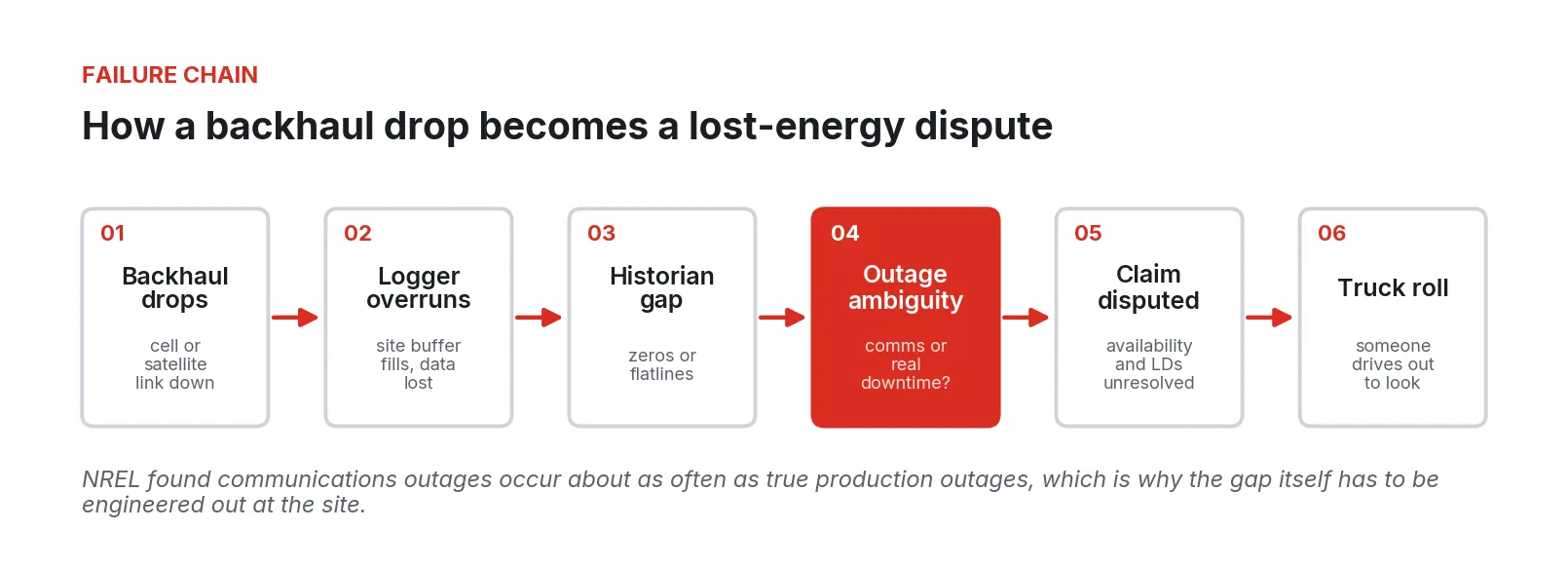
Figure 2. The failure chain that turns a dropped link into a disputed claim. The ambiguity at step four is what store-and-forward and network monitoring remove. Source for the note: NREL (2020).
A reference architecture
The design principle: the site runs, records, and defends itself as if the backhaul did not exist, and the fleet catches up automatically when it returns.
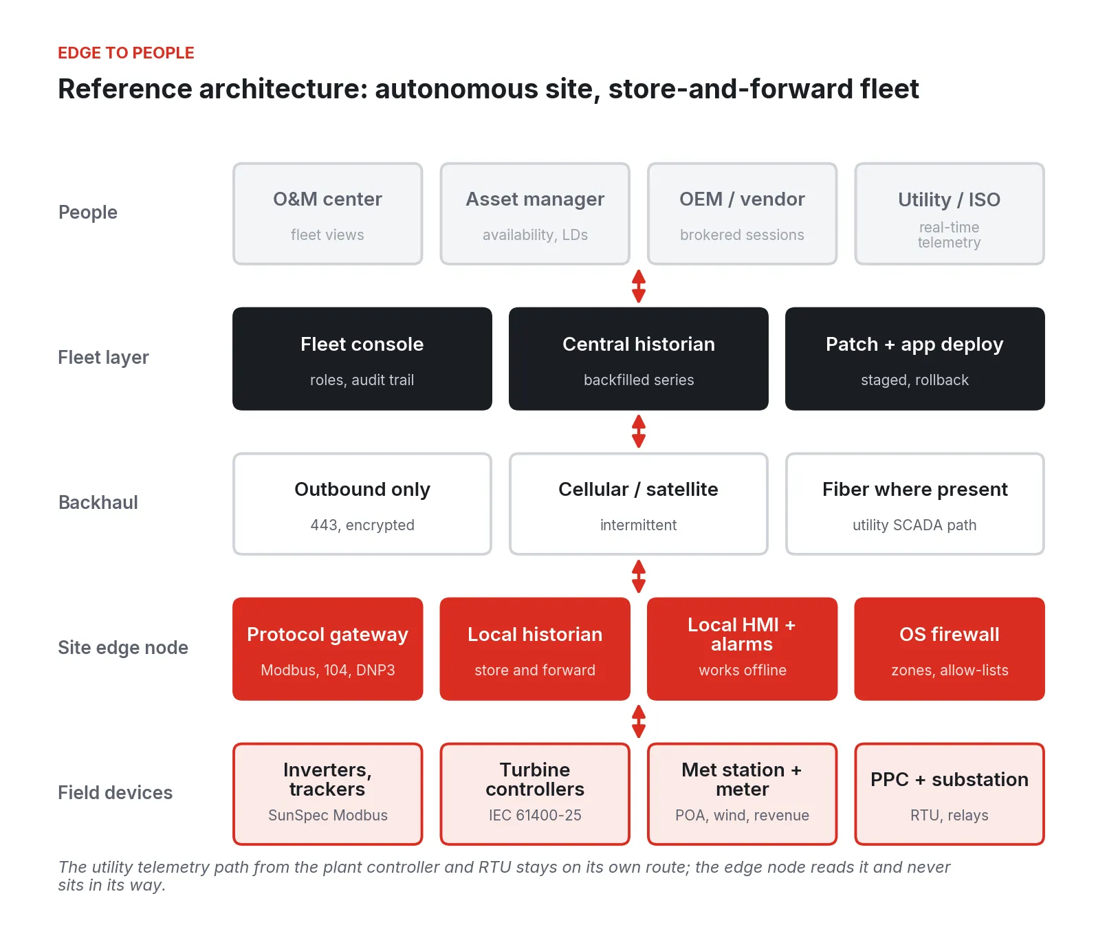
Figure 3. Reference architecture for a remote solar or wind site. Field devices feed a site edge node that keeps running and recording offline; data moves outbound to the fleet layer when the link allows.
Field devices stay as they are
Field equipment keeps doing its job, and nothing here changes a setpoint path the interconnection agreement depends on. The plant controller’s link to the utility or ISO, and the RTU’s DNP3 path, stay on their own routes. The edge layer reads those devices as a client; it does not sit between them and the grid operator.
A site edge node does four jobs
1. Protocol gateway. One place that polls SunSpec and vendor Modbus maps, reads the OEM turbine SCADA over IEC 61400-25 or the OEM’s export, and pulls DNP3 from the meter and RTU. Tags get one naming convention across the fleet at this layer, not in the central historian.
2. Local historian with store and forward. Every value is written locally first, with its own timestamp, then forwarded. When the link drops, the site keeps writing for days or weeks instead of the hours a logger buffer holds. When the link returns, the backlog flows up in order and the central historian backfills the gap.
3. Local HMI and alarming. A technician on site, or the O&M center over a working link, sees the same screens. Alarms are evaluated at the site, so a breaker trip at 2 a.m. raises an alarm even if the central server cannot see the site.
4. Segmentation. The inverter network, turbine network, met and meter network, plant controller, and substation each sit in their own zone, with explicit allow-lists between them and out of the site.
Backhaul: plan for the link to fail
Most remote sites run on cellular, sometimes with satellite as backup; plan for both to fail. The EPRI and Sandia O&M budgeting guide notes that problems with communications uptime have already pushed owners toward redundant links and battery backup for the communications equipment, because the measurements matter. Put the modem, switch, and edge node on a UPS that outlasts a typical grid event, and make every site connection outbound. A site that only dials out needs no public IP address or port-forward on a carrier modem.
The fleet layer
The central side is a fleet console, a historian that accepts backfilled data, and staged patch and app deployment with rollback. The O&M center, asset managers, OEM service engineers, and the utility each get a role-scoped view of the same data.
Doing the work, cheapest fixes first
The order matters. The first three steps cost little and pay back on the next availability report.
Step 1: Instrument the network itself
Before touching SCADA software, monitor the communications equipment: modem signal and session uptime, switch ports, UPS state, and a heartbeat from each logger, mostly available over SNMP. Store it beside the generation data, and every historian gap can be tagged “link down”, “device down”, or “both”.
Step 2: Put the revenue meter beside every inverter channel
Pull 15-minute or 5-minute energy from the revenue meter into the same historian as the inverter data, and compute a simple check: sum of inverter energy against meter energy, per interval. Where the inverter sum drops to zero and the meter does not, the interval is a data gap. This is the same logic NREL uses in its fleet availability method, and it can be done in a spreadsheet for the first month.
Step 3: Fix the clocks
Event analysis across inverters, turbines, the plant controller, and relays depends on timestamps agreeing; NREL screened every stream in its fleet study for time shift and time zone errors. Set one time source per site, confirm each device’s time zone and daylight-saving handling, and record which devices timestamp at the source.
Step 4: Add local storage and store-and-forward
Supplement the logger’s short buffer with a local historian that holds weeks of data and forwards in order. Size it for the longest outage you have seen, times three.
Step 5: Normalize tags across OEMs
Map each inverter model, tracker controller, and turbine type to one fleet tag model at the edge. Use SunSpec 700-series points where the inverter supports them, and the IEC 61400-25 logical nodes as the naming pattern for turbines even when the data arrives through an OEM export. This is integration work on each controller’s registers or tags, and it is the step EPC handover packages most often skip.
Step 6: Segment and broker remote access
Draw the zones, write the allow-lists, and route every vendor connection through one path that logs who connected, to what, and when, and that can be shut off from the console. This is the step that lines up with CIP-003-9, covered below.
Step 7: Replace the aging pieces on your schedule
The EPC-delivered SCADA server is often a single PC whose image nobody else has. Once the edge and central historian carry the data, it can be retired when it fails instead of rebuilt in a hurry.
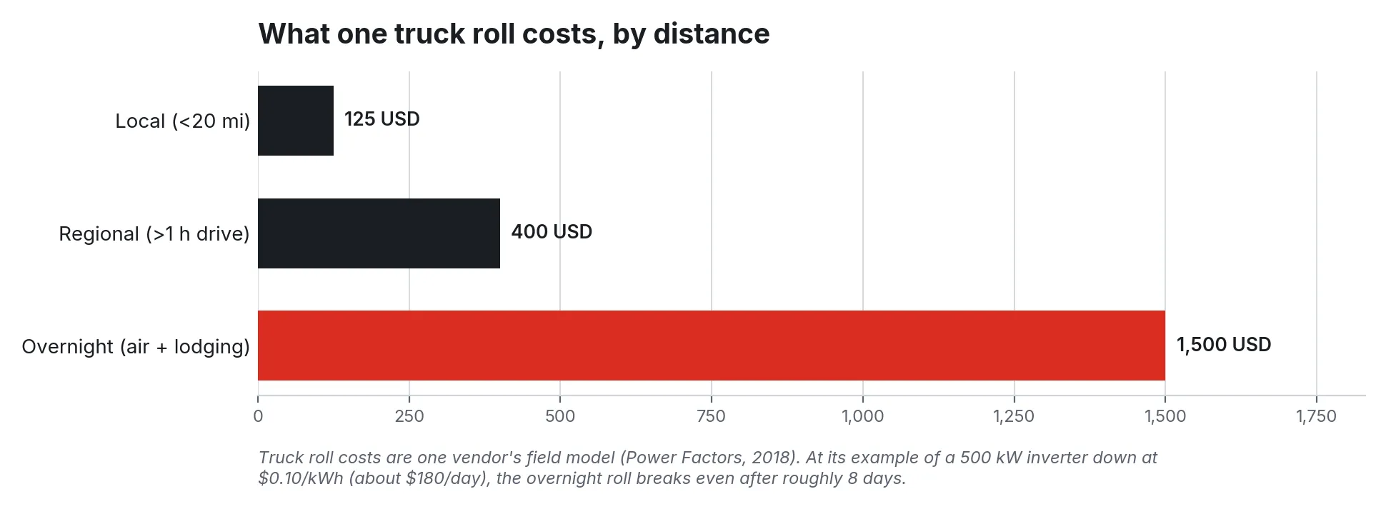
Figure 4. What a single truck roll costs depending on distance, in one vendor’s cost model. Remote wind and solar sites usually sit in the regional or overnight band. Source: Power Factors (2018).
The truck-roll math is what makes Steps 1 through 4 pay. In one vendor’s field model, a local call costs about $125, a regional drive of more than an hour about $400, and an overnight trip with air travel and lodging about $1,500. Its worked example, a 500 kW inverter down at $0.10 per kWh, loses roughly $180 a day, so an overnight trip to reset that inverter only breaks even after about eight days of lost revenue. Data that shows whether the inverter or the modem is down turns that eight-day decision into a same-day one, or cancels the trip.
For budget context, NREL’s 2024 Annual Technology Baseline puts utility-scale PV fixed O&M at about $22 per kWac-year, and NREL’s Cost of Wind Energy Review puts land-based wind operating expenditure at about $43 per kW-year, with Berkeley Lab identifying turbine O&M as its largest component. Truck rolls and diagnosis time come out of those numbers.
Where these projects go wrong
1. The historian is fixed, but the gap is upstream. A new central historian does nothing for data the site never stored.
2. Communications outages are counted as availability losses, or the reverse. NREL found the two happen at similar frequency. Without network monitoring and a meter cross-check, availability numbers are wrong in both directions.
3. Data quality is assumed. NREL could only use about four in five of the PV systems it collected, after screening for time shifts and bad channels. Fleets that skip this step build dashboards on data that would not survive a dispute.
4. The OEM keeps its own path in. A turbine or inverter vendor installs its own modem or VPN appliance for remote service. It works, nobody records it, and it bypasses every control the owner has. The DOE wind cybersecurity roadmap notes that the remote location of wind plants often pushes control applications onto internet-facing connections.
5. Flat networks. Fieldbus protocols used inside turbines and inverter blocks, such as Modbus, pass data in clear text and can be spoofed, as the same DOE roadmap points out. If a laptop plugged into a tracker cabinet can reach the plant controller, segmentation does not exist.
6. The edge layer is put in the utility’s path. An integrator routes plant controller setpoints or RTU telemetry through the new gateway to “simplify” things, and now a software update on the gateway can affect interconnection compliance. Keep those paths separate.
7. Standardization stops at the first site. The second site gets a different tag map, firewall, and historian because a different EPC built it, and the fleet layer never pays off.
8. Patching is never done. Remote boxes with no rollback plan stay unpatched, because a failed patch means a truck roll.
Security and compliance in NERC CIP terms
Applicability first. Under NERC CIP-002, generation becomes medium impact mainly through aggregate size or designation: shared BES Cyber Systems that could, within 15 minutes, adversely affect 1,500 MW or more at a single plant location; generation designated by the Planning Coordinator or Transmission Planner as needed to avoid an adverse reliability impact; generation critical to IROLs; and Generator Operator control centers controlling 1,500 MW or more. Generation that meets none of the high or medium criteria is low impact. Most individual solar and wind plants land in low impact. A GOP control center running a large fleet can cross the 1,500 MW line even when no single plant does, so check the control center separately.
The registered population is also growing. NERC’s Category 2 registration brings in inverter-based resources of 20 MVA or more at a common point of connection at 60 kV or above, with registrations listed on the compliance registry as of May 15, 2026. Many sites that sat outside the registry are now inside it.
For low impact assets, CIP-003-9 is the operative standard, and it became effective April 1, 2026. Its Attachment 1 sets out what the plan must cover. Two sections drive the architecture.
1. Section 3, electronic access controls. For routable communications into or out of the asset containing low impact BES Cyber Systems, permit only necessary inbound and outbound access, with a documented business justification, and authenticate dial-up where the device allows. ReliabilityFirst’s guidance adds change control on the access devices, periodic review of configurations, and examining traffic to confirm the controls work as designed.
2. Section 6, vendor electronic remote access. New in CIP-003-9: a method to determine or identify vendor remote access, a method to disable it, and a method to detect malicious communications, inbound and outbound. ReliabilityFirst suggests treating non-employees as vendors unless they meet employee-equivalent screening and training. Industry commentary for solar owners notes that inverter controls, plant controllers, SCADA, and data acquisition systems all fall in scope, and that the common gap is evidence and documentation more than technical capability.
Two related signals point the same way. NERC’s Level 2 alert of June 17, 2025 asked Generator Owners and Operators to inventory remote access to bulk power system elements originating outside the continental United States and to document each connection; multi-OEM fleets with overseas service centers had to answer it. And FERC Order 901 directed NERC to develop standards requiring that inverter-based resource owners share validated operations and disturbance-monitoring data, with filings phased through November 2026. Data that never left the site cannot be shared.
The site’s compliance program owns the plan, the evidence, and the attestation. The table shows where the architecture supports each control.
| CIP-003-9 element | What the architecture provides |
|---|---|
| Section 3: only necessary inbound and outbound access | Outbound-only site connections, no inbound ports, explicit allow-lists between zones and out of the site |
| Section 3: change control and periodic review | Firewall configuration managed centrally and versioned, with changes recorded in an audit trail |
| Section 6: identify vendor remote access | Every OEM and contractor session goes through one brokered path, tied to a named identity and logged |
| Section 6: disable vendor remote access | Sessions and accounts can be revoked from the console; no separate vendor modem left to unplug |
| Section 6: detect malicious communications | Zone boundaries at each node create defined points to log and inspect traffic between field networks and out of the site |
Rolling it out
Figure 5. A phased rollout. Assessment and one representative site come first; the fleet build follows only once the site template is proven.
1. Phase 0, assess (two to four weeks). For every site: device inventory with protocols and firmware, backhaul type and last twelve months of outages, historian gap report, every remote access path including OEM-owned ones, and the current CIP-002 categorization. Rank sites by lost data and truck rolls.
2. Phase 1, one site. Pick a site with multiple OEMs, a weak link, and a known gap. Install the edge node in front of existing equipment, add store-and-forward, monitor the network, cross-check the meter, draw the zones, and confirm the backfill through a real outage.
3. Phase 2, vendor access. Move each OEM and contractor onto the brokered path one at a time, with the vendor’s cooperation, and remove their private modems or appliances as each one moves. Write the CIP-003-9 Section 6 procedures against what is actually running.
4. Phase 3, fleet. Repeat the Phase 1 template, same tag model, zones, and apps, at every site in Phase 0 rank order, from one console.
5. Phase 4, retire technical debt. As EPC-era SCADA PCs, loggers, and HMIs fail or reach end of support, move their functions into apps on the node, on your schedule.
What to do Monday
Pick the site you argue about most. Pull last quarter’s availability report and mark every interval where an inverter or turbine reads zero. Pull the revenue meter data for the same intervals and split them into “meter also low” and “meter normal”. Then pull the modem’s uptime log, if it has one, and line it up. In a day you will know how much of your reported downtime was real, how much was the network, and how much you cannot tell. Then list every way a vendor can reach that site and have each vendor confirm it. Those two pages are the business case and the CIP-003-9 Section 6 starting point.
None of this requires a new platform to begin. It requires one site, a month of data, and the discipline to write down what you find.
Fireball Industries is EmberNet’s master integrator. Fireball designs, builds, and supports this work for owners and operators of solar and wind fleets: the site assessment, the edge build in front of existing inverters, turbines, and plant controllers, the vendor access path, the fleet rollout, and the long tail of support once the sites are running.
Sources
- Deline, C., Muller, M., White, R., Perry, K., Springer, M., Deceglie, M., Jordan, D. (NREL). “Availability and Performance Loss Factors for U.S. PV Fleet Systems,” NREL/TP-5K00-88769, February 2024. https://docs.nlr.gov/docs/fy24osti/88769.pdf
- National Renewable Energy Laboratory. “Overcoming Communications Outages in Inverter Downtime Analysis: Preprint,” NREL/CP-5K00-76022, 47th IEEE Photovoltaic Specialists Conference, 2020. https://research-hub.nlr.gov/en/publications/overcoming-communications-outages-in-inverter-downtime-analysis-p/
- Gunda, T., Hackett, S., Kraus, L., Downs, C., Jones, R., McNalley, C., Bolen, M., Walker, A. (Sandia/NREL). “A Machine Learning Evaluation of Maintenance Records for Common Failure Modes in PV Inverters,” November 2020. https://docs.nlr.gov/docs/fy21osti/78736.pdf
- Enbar, N., Weng, D. (EPRI), Klise, G. (Sandia). “Budgeting for Solar PV Plant Operations & Maintenance: Practices and Pricing,” SAND2015-10851R, December 2015. https://www.osti.gov/servlets/purl/1234935
- National Renewable Energy Laboratory. “Utility-Scale PV,” Annual Technology Baseline 2024. https://atb.nlr.gov/electricity/2024/utility-scale_pv
- Wiser, R., Bolinger, M., Seel, J. (Berkeley Lab). “Benchmarking Utility-Scale PV Operational Expenses and Project Lifetimes: Results from a Survey of U.S. Solar Industry Professionals,” June 2020. https://emp.lbl.gov/publications/benchmarking-utility-scale-pv
- Stehly, T., Duffy, P., Mulas Hernando, D. (NREL). “Cost of Wind Energy Review: 2024 Edition,” November 2024. https://docs.nlr.gov/docs/fy25osti/91775.pdf
- Wiser, R., Bolinger, M., Lantz, E. (Berkeley Lab). “Benchmarking Wind Power Operating Costs in the United States: Results from a Survey of Wind Industry Experts,” January 2019. https://emp.lbl.gov/publications/benchmarking-wind-power-operating
- Hanawalt, S. (Power Factors). “The 10 Things You Need to Know to De-risk Solar O&M, #4: Know Your Break-Even Truck Roll Cost,” August 14, 2018 (vendor source). https://www.powerfactors.com/blog/the-10-things-you-need-to-know-to-de-risk-solar-om-4-know-your-break-even-truck-roll-cost
- SunSpec Alliance. “SunSpec Modbus 700 Series DER Information Models are now APPROVED,” April 21, 2021. https://sunspec.org/sunspec-modbus-700-series-der-information-models-are-now-approved/
- SunSpec Alliance. “SunSpec Modbus IEEE 1547-2018 Profile Specification and Implementation Guide,” v1.1, February 15, 2024. https://sunspec.org/wp-content/uploads/2025/01/SunSpec-Modbus-IEEE-1547-2018-Profile-Specification-and-Implementation-Guide-v1.1-1.pdf
- International Electrotechnical Commission. “IEC 61400-25-1:2017, Wind energy generation systems, Part 25-1: Communications for monitoring and control of wind power plants, Overall description of principles and models,” Edition 2.0, July 2017 (preview). https://cdn.standards.iteh.ai/samples/22989/11fcec1ff2b84515bf8f8202441f6545/IEC-61400-25-1-2017.pdf
- Wikipedia. “IEC 61400-25,” accessed September 2026. https://en.wikipedia.org/wiki/IEC_61400-25
- North American Electric Reliability Corporation. “CIP-002-5.1a, Cyber Security, BES Cyber System Categorization.” https://www.nerc.com/globalassets/standards/reliability-standards/cip/cip-002-5.1a.pdf
- Folkerth, L. (ReliabilityFirst). “The Lighthouse: CIP Low Impact from the Ground Up, Part 8.3.9: Electronic Access Controls for CIP-003-9,” updated August 19, 2026. https://www.rfirst.org/resource-center/the-lighthouse-cip-low-impact-from-the-ground-up-part-8-3-9-electronic-access-controls-for-cip-003-9/
- Ware, B. (pv magazine USA). “Navigating the new NERC requirements for vendor remote access,” April 22, 2026. https://pv-magazine-usa.com/2026/04/22/navigating-the-new-nerc-requirements-for-vendor-remote-access/
- Firestone, J. (pv magazine USA). “NERC inverter-based resource registration initiative enters final stretch for asset owners,” May 14, 2026. https://pv-magazine-usa.com/2026/05/14/nerc-inverter-based-resource-registration-initiative-enters-final-stretch-for-asset-owners/
- Midwest Reliability Organization. “Recommendation To Industry on NERC Level 2 Alert: Cross-Border Remote Access to Bulk Power System Elements,” 2025. https://www.mro.net/recommendation-to-industry-on-nerc-level-2-alert-cross-border-remote-access-to-bulk-power-system-elements/
- Federal Energy Regulatory Commission. “Reliability Standards To Address Inverter-Based Resources,” Order No. 901, Federal Register, October 30, 2023. https://www.federalregister.gov/documents/2023/10/30/2023-23581/reliability-standards-to-address-inverter-based-resources
- U.S. Department of Energy (with INL, NREL, Sandia). “Roadmap for Wind Cybersecurity,” July 2020. https://www.energy.gov/sites/prod/files/2020/07/f76/wind-energy-cybersecurity-roadmap-2020v2.pdf